INDRBT / Reading room
CAD component catalog
Adapted for browser reading from the project’s illustrated documentation. Numeric results and engineering scope are unchanged. Reproduction notes are optional; the robot and board viewers run from the navigation above.
On this page
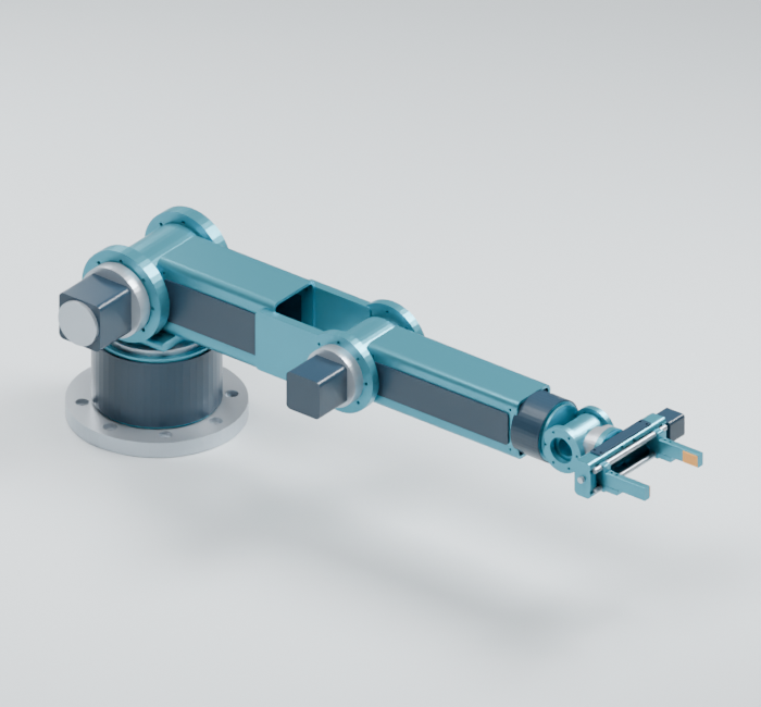
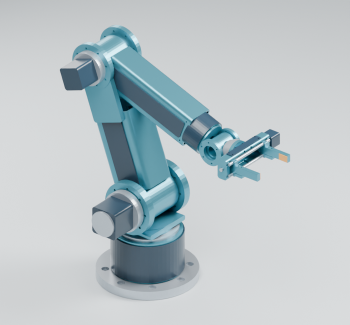
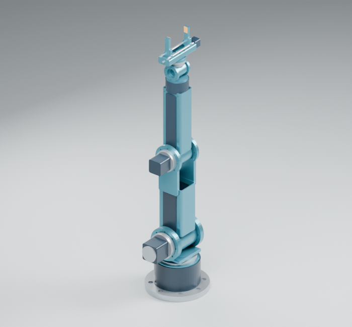
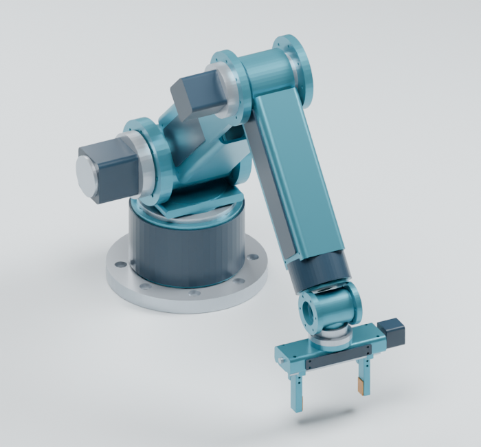
INDRBT has 54 original modeled components and six complete pose assemblies. This catalog connects each part to its assembly role, assumed material, individual models and saved FreeCAD object. All CAD lengths are in millimetres.
Open the robot
| What you want | Open this | How to use it |
|---|---|---|
| Move the assembled robot | Interactive 3D viewer | Download the repository and open the HTML in a browser; use the pose selector, joint controls, gripper slider and play button. GitHub displays HTML source. |
| Inspect the solid home assembly | FreeCAD native assemblySource file | Open with FreeCAD. Its 54 saved solid objects are cross-referenced below. |
| Inspect the rendering scene | Blender native sceneSource file | Open with Blender. Robot object names match the component filenames. |
| See the mechanism quickly | Home render, gripper close-up, six-pose sheet | Ordinary image previews. |
| Read interface dimensions | Three-page drawing PDF | Concept dimensions for the base/flange, link sections and gripper. |
| Change the design parameters | SI configuration, parametric geometry sourceSource file, CAD methodology | Regenerate from the Python source after changing parameters. The saved FreeCAD assembly contains solid geometry; the Python source defines the parametric construction. |
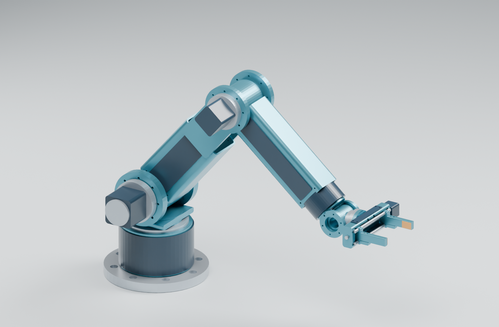
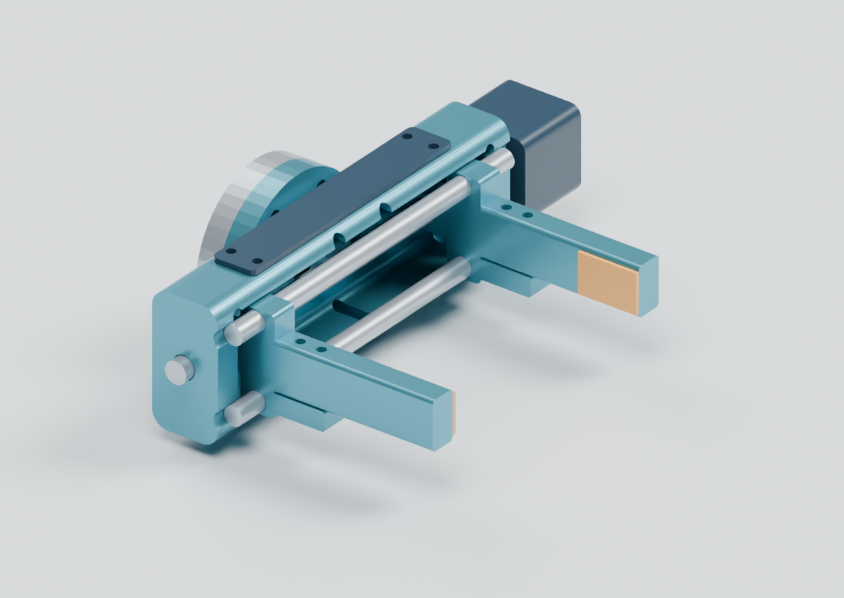
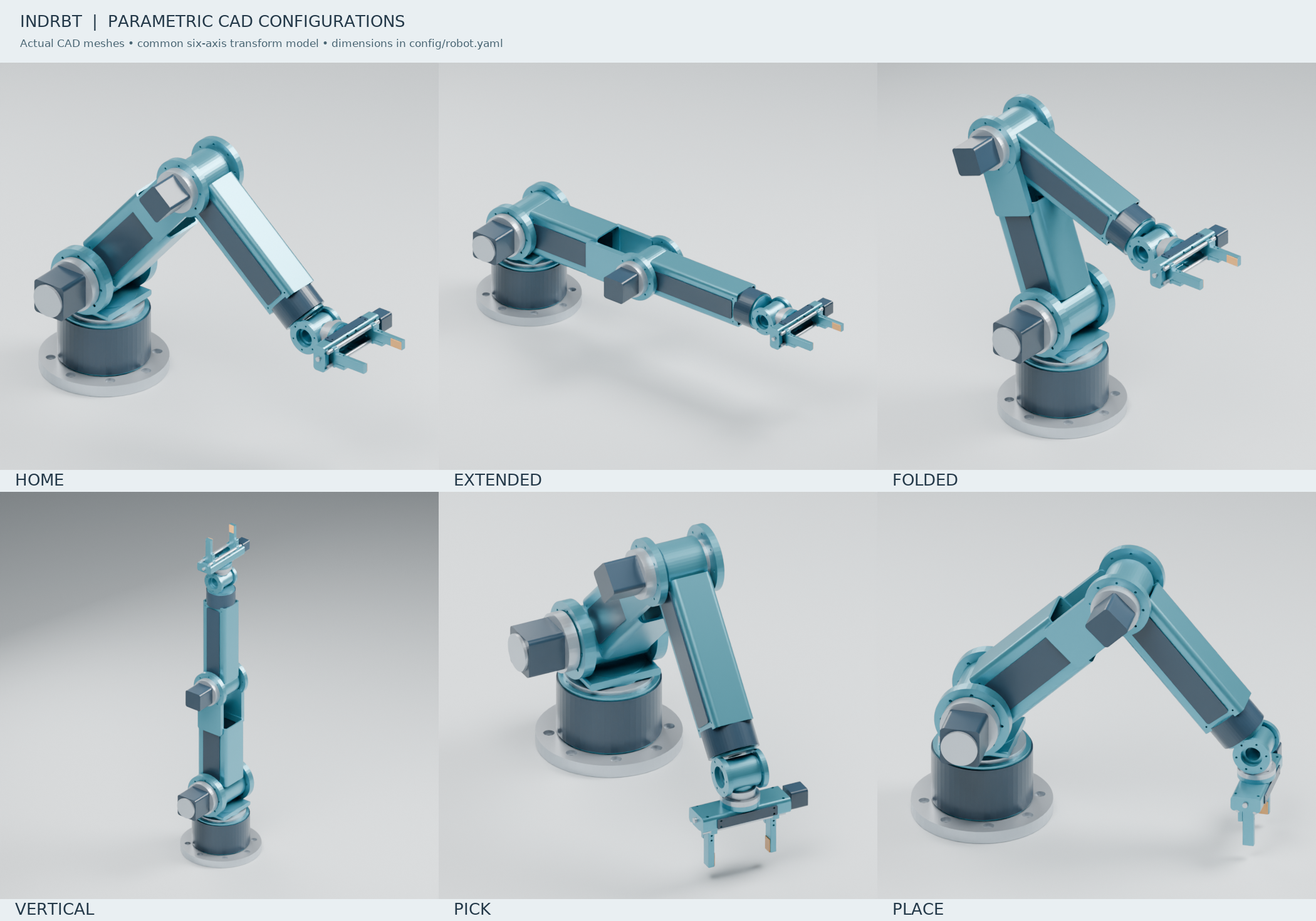
In the organized project folder, double-click OPEN_3D_VIEWER.cmd or OPEN_FREECAD_MODEL.cmd to open the installed application. The same files are copied under 01_CAD_Models; component STEP files are in STEP/Individual_Parts, and complete poses are in STEP/Assemblies.
STEP files preserve solid geometry for CAD inspection and exchange. STL files contain triangles for mesh viewers and printing preparation. Component exports remain in their local assembly-group frame; open a complete pose to see all parts together.
Complete assemblies
| Pose | Joint angles in degrees, J1 to J6 | Solid CAD | Mesh | Preview |
|---|---|---|---|---|
| Home | 0, -50, 90, 0, -40, 0 | STEPSource file | STLSource file | Image |
| Extended | 0, 0, 0, 0, 0, 0 | STEPSource file | STLSource file | Image |
| Folded | 0, -110, 130, 0, -20, 0 | STEPSource file | STLSource file | Image |
| Vertical | 0, -90, 0, 0, 0, 0 | STEPSource file | STLSource file | Image |
| Pick | -25, -45, 95, 0, 40, 0 | STEPSource file | STLSource file | Image |
| Place | 25, -45, 95, 0, 40, 0 | STEPSource file | STLSource file | Image |
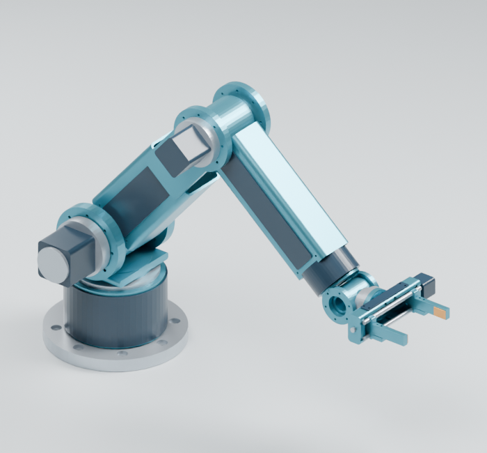
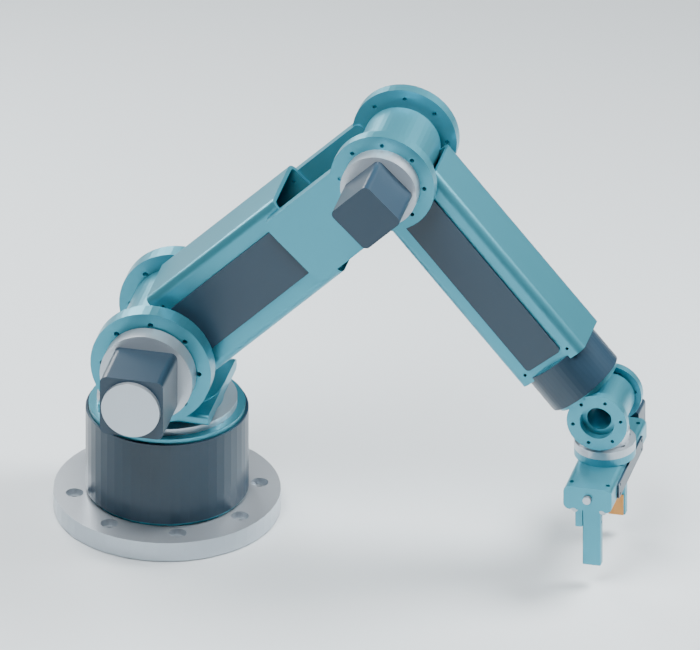
Find an individual component
The group labels base, j1 to j6 identify moving coordinate frames. A motor name such as j2_motor_envelope identifies the actuator it represents; its housing belongs to the preceding support frame. Names ending -1 and +1 mark the two side instances. Gripper guide rods ending -14 and +14 are at local Z = -14 and +14 mm.
An envelope is a simplified spatial placeholder for a motor, gearbox, bearing or screw. Its interior is not a detailed purchased component. Materials are assumed; the geometric mass estimate is separate from the conservative dynamic mass inputs.
FreeCAD objects retain Component01 to Component54 internal names and display the descriptive component label. The mapping below was checked against the individual part volumes and home-assembly positions. Blender and individual exports retain the descriptive part names.
Fixed base (base; 4 parts)
Mounting plate, hollow riser and fixed covers.
| Component / filename | Assembly role | Assumed material | FreeCAD object | Individual model |
|---|---|---|---|---|
base_mounting_plate |
Structure | Steel | Component01 |
STEPSource file / STLSource file |
fixed_base_riser |
Structure | Aluminum | Component02 |
STEPSource file / STLSource file |
j1_slew_bearing_envelope |
Bearing envelope | Steel | Component03 |
STEPSource file / STLSource file |
base_electronics_cover |
Removable cover | Polymer | Component04 |
STEPSource file / STLSource file |
Turret and shoulder support (j1; 9 parts)
Rotates around J1; supports the shoulder bearing and J2 actuator housing.
| Component / filename | Assembly role | Assumed material | FreeCAD object | Individual model |
|---|---|---|---|---|
turret_neck |
Structure | Aluminum | Component05 |
STEPSource file / STLSource file |
turret_bridge |
Structure | Aluminum | Component06 |
STEPSource file / STLSource file |
shoulder_fork_-1 |
Structure | Aluminum | Component07 |
STEPSource file / STLSource file |
shoulder_bearing_-1 |
Bearing envelope | Steel | Component08 |
STEPSource file / STLSource file |
shoulder_fork_+1 |
Structure | Aluminum | Component09 |
STEPSource file / STLSource file |
shoulder_bearing_+1 |
Bearing envelope | Steel | Component10 |
STEPSource file / STLSource file |
j2_gearbox_envelope |
Gearbox envelope | Steel | Component11 |
STEPSource file / STLSource file |
j2_motor_envelope |
Motor envelope | Polymer | Component12 |
STEPSource file / STLSource file |
j2_motor_endcap |
Motor end cap | Steel | Component13 |
STEPSource file / STLSource file |
Upper arm and elbow support (j2; 13 parts)
Rotates around J2; carries the upper link, elbow clevis, bearings and J3 actuator housing.
| Component / filename | Assembly role | Assumed material | FreeCAD object | Individual model |
|---|---|---|---|---|
shoulder_rotor |
Structure | Aluminum | Component14 |
STEPSource file / STLSource file |
shoulder_output_shaft |
Hollow output shaft | Steel | Component15 |
STEPSource file / STLSource file |
upper_arm_hollow_link |
Structure | Aluminum | Component16 |
STEPSource file / STLSource file |
elbow_fork_bridge_-1 |
Structure | Aluminum | Component17 |
STEPSource file / STLSource file |
elbow_fork_bridge_+1 |
Structure | Aluminum | Component18 |
STEPSource file / STLSource file |
upper_service_cover_-1 |
Service cover | Polymer | Component19 |
STEPSource file / STLSource file |
elbow_fork_-1 |
Structure | Aluminum | Component20 |
STEPSource file / STLSource file |
elbow_bearing_-1 |
Bearing envelope | Steel | Component21 |
STEPSource file / STLSource file |
upper_service_cover_+1 |
Service cover | Polymer | Component22 |
STEPSource file / STLSource file |
elbow_fork_+1 |
Structure | Aluminum | Component23 |
STEPSource file / STLSource file |
elbow_bearing_+1 |
Bearing envelope | Steel | Component24 |
STEPSource file / STLSource file |
j3_gearbox_envelope |
Gearbox envelope | Steel | Component25 |
STEPSource file / STLSource file |
j3_motor_envelope |
Motor envelope | Polymer | Component26 |
STEPSource file / STLSource file |
Forearm and wrist roll support (j3; 8 parts)
Rotates around J3; carries the forearm and stationary wrist roll housing/cover.
| Component / filename | Assembly role | Assumed material | FreeCAD object | Individual model |
|---|---|---|---|---|
elbow_rotor |
Structure | Aluminum | Component27 |
STEPSource file / STLSource file |
elbow_output_shaft |
Hollow output shaft | Steel | Component28 |
STEPSource file / STLSource file |
forearm_hollow_link |
Structure | Aluminum | Component29 |
STEPSource file / STLSource file |
forearm_service_cover_-1 |
Service cover | Polymer | Component30 |
STEPSource file / STLSource file |
forearm_service_cover_+1 |
Service cover | Polymer | Component31 |
STEPSource file / STLSource file |
wrist_roll_stator |
Structure | Aluminum | Component32 |
STEPSource file / STLSource file |
j4_bearing_envelope |
Bearing envelope | Steel | Component33 |
STEPSource file / STLSource file |
wrist_roll_cover |
Cover | Polymer | Component35 |
STEPSource file / STLSource file |
Wrist roll rotor and pitch supports (j4; 3 parts)
Rotates around J4; the roll output carries the pitch fork.
| Component / filename | Assembly role | Assumed material | FreeCAD object | Individual model |
|---|---|---|---|---|
wrist_roll_rotor |
Structure | Aluminum | Component34 |
STEPSource file / STLSource file |
wrist_pitch_fork_-1 |
Structure | Aluminum | Component36 |
STEPSource file / STLSource file |
wrist_pitch_fork_+1 |
Structure | Aluminum | Component37 |
STEPSource file / STLSource file |
Wrist pitch link (j5; 3 parts)
Rotates around J5; carries the pitch neck and final roll stator.
| Component / filename | Assembly role | Assumed material | FreeCAD object | Individual model |
|---|---|---|---|---|
wrist_pitch_rotor |
Structure | Aluminum | Component38 |
STEPSource file / STLSource file |
wrist_pitch_neck |
Structure | Aluminum | Component39 |
STEPSource file / STLSource file |
j6_stator_envelope |
Gearbox envelope | Steel | Component40 |
STEPSource file / STLSource file |
Tool flange and parallel gripper (j6; 14 parts)
Rotates around J6; the two gripper jaw families additionally translate along local Y.
| Component / filename | Assembly role | Assumed material | FreeCAD object | Individual model |
|---|---|---|---|---|
tool_flange_6xM5_PCD46 |
Structure | Steel | Component41 |
STEPSource file / STLSource file |
interchangeable_gripper_adapter |
Structure | Aluminum | Component42 |
STEPSource file / STLSource file |
gripper_pocketed_body |
Structure | Aluminum | Component43 |
STEPSource file / STLSource file |
gripper_top_service_cover |
Service cover | Polymer | Component44 |
STEPSource file / STLSource file |
gripper_guide_rod_-14 |
Linear guide | Steel | Component45 |
STEPSource file / STLSource file |
gripper_guide_rod_+14 |
Linear guide | Steel | Component46 |
STEPSource file / STLSource file |
opposite_hand_screw_envelope |
Opposite hand screw envelope | Steel | Component47 |
STEPSource file / STLSource file |
gripper_actuator_envelope |
Motor envelope | Polymer | Component48 |
STEPSource file / STLSource file |
gripper_jaw_carriage_-1 |
Structure | Aluminum | Component49 |
STEPSource file / STLSource file |
gripper_finger_-1 |
Structure | Aluminum | Component50 |
STEPSource file / STLSource file |
gripper_contact_pad_-1 |
Replaceable contact pad | Polymer | Component51 |
STEPSource file / STLSource file |
gripper_jaw_carriage_+1 |
Structure | Aluminum | Component52 |
STEPSource file / STLSource file |
gripper_finger_+1 |
Structure | Aluminum | Component53 |
STEPSource file / STLSource file |
gripper_contact_pad_+1 |
Replaceable contact pad | Polymer | Component54 |
STEPSource file / STLSource file |
Gripper motion and checked scope
The two contact pads have 90 mm clear separation at maximum opening and touch at zero opening. Each jaw moves 45 mm; its carriage, finger and contact pad move together along local Y. The guide rods, body, screw envelope and actuator remain fixed in the tool frame. The saved component files show maximum opening; the interactive viewer applies the symmetric jaw translation.
The final review checked the pad gaps and jaw/body intersections at 0, 22.5, 45, 67.5 and 90 mm openings. The retained assembly screen checks every component pair at six poses and the closed/mid/open gripper. The trajectory screen checks 75 representative configurations. These finite digital checks do not certify every joint-angle combination or continuous physical motion.
See final component review, native release consistency, CAD properties, assembly clearance and trajectory clearance for the executed evidence. Drawings are concept interfaces without production tolerances.