INDRBT / Reading room
INDRBT engineering report
Adapted for browser reading from the project’s illustrated documentation. Numeric results and engineering scope are unchanged. Reproduction notes are optional; the robot and board viewers run from the navigation above.
On this page
- INDRBT engineering report
- 1. Abstract
- 2. Problem
- 3. Requirements
- 4. Mechanical architecture
- 5. CAD methodology
- 6. Kinematic model
- 7. Workspace
- 8. Gripper
- 9. Mechanical calculations
- 10. Actuator sizing
- 11. Motion planning
- 12. Control system
- 13. Electronics architecture
- 14. Simulation
- 15. Verification
- 16. Results and research questions
- 17. Limitations
- 18. Future work
- 19. Conclusion
Version 1.2.0 · 2026-10-05 · digital engineering project
1. Abstract
INDRBT is an original six-axis industrial-arm concept with reproducible BRep CAD, numerical kinematics, motion planning, a parallel gripper, load calculations and a native conceptual KiCad interface. Its nominal shoulder-centred reach is 790 mm. The 4 kg payload and ±0.1 mm repeatability are design targets; neither is a tested hardware rating. The project is an educational geometric digital twin whose evidence comes from executed software.
2. Problem
Build a credible small manipulator without copying a commercial design or constructing hardware. Engineering depth comes from consistent geometry/transforms, actual simulation, numerical reconstruction, independent checks and documented tradeoffs. The supplied task is a simple bench pick-and-place cycle.
3. Requirements
The requirements specify six revolute joints and 600–800 mm nominal reach. The selected design has a 90 mm gripper opening and a 4 kg payload target. Configured speed and acceleration limits, FK/IK/Jacobian checks, reproducible motion/control experiments and evidence-linked documentation complete the digital scope. The validation matrix separates verified digital checks from unverified performance targets.
4. Mechanical architecture
A rotating turret, shoulder clevis, hollow upper arm, elbow clevis, hollow forearm and X-Y-X wrist carry an original 60 mm tool flange. Six M5 clearance holes on a 46 mm pitch circle and a central pilot/adapter provide an interchangeable interface. Compatibility with a commercial flange standard is unverified. Covers, bearing seats, cable bores, guide rods and actuator envelopes give the geometry an engineering purpose.
5. CAD methodology
Build123d 0.13.0 creates 54 valid BRep components from centralized SI inputs, converted explicitly to millimetres. The 6 configured assemblies export STEP/STL. STEP reimports preserve the reported component counts; the maximum relative volume discrepancy is 1.160e-09. CAD joint placements match the software transforms, with maximum matrix-entry discrepancy 3.331e-16. FreeCAD independently imports the exports, and Blender renders their tessellated geometry. Dimension sheets describe interfaces and nominal sections; manufacturing tolerances remain open. See CAD methodology.
6. Kinematic model
The chain is Tz(h)Rz(q1)Ry(q2)Tx(L1)Ry(q3)Tx(L2)Rx(q4)Tx(wr)Ry(q5)Tx(wp)Rx(q6)Tx(tool). FK produces TCP pose. The world geometric Jacobian stacks axis cross TCP displacement and axis direction. Numerical least-squares IK uses bounded joints, translation scaled by reach and SO(3) logarithmic orientation residuals, plus multiple starts and residual verification. Kinematics defines every frame, limit and singularity caveat.
7. Workspace
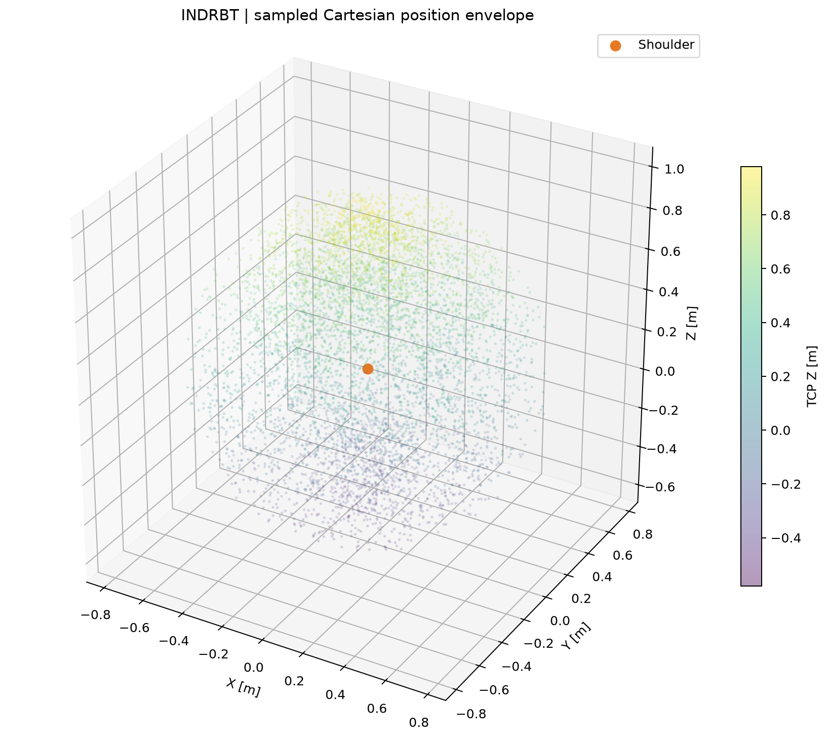
The 6000 seeded joint samples reach a maximum sampled shoulder radius of 0.789744 m, compared with the 790 mm nominal reach. Of these samples, 4293 place the TCP above the base plane. The 1.902506 m³ convex hull fills inaccessible holes, so it is an envelope rather than a reachable or collision-free volume. The dimensionless smallest Jacobian singular value is below 0.01 in 8.05% of samples. This is a geometric conditioning indicator, not a safety threshold. Workspace plots and raw data preserve the sampling details.
8. Gripper
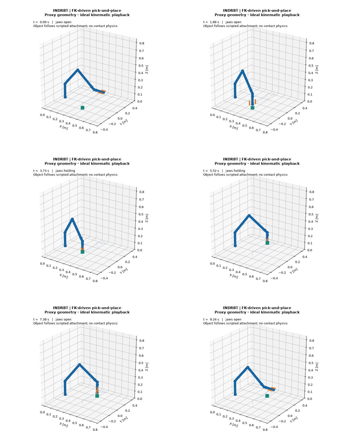
Two guided jaws use an opposed-hand screw concept. A 90 mm opening requires 45 mm travel per jaw, or 11.25 revolutions at a 4 mm lead. The 200 N total normal-force target requires a calculated 0.363783 N·m at assumed efficiency 0.35. The ideal friction-only payload estimate is 5.099 kg, using μ = 0.5 and safety factor 2. Contact pressure, backlash, guide friction and force control remain unmodelled. The animated object is a task token whose visual size does not establish a physical mass or density.
9. Mechanical calculations
The assumed manipulator mass is 23.65 kg; the separate summed CAD envelope/material estimate is 19.908 kg. Midpoint COM gravity loading at full extension with a 4 kg payload gives shoulder holding torque of 70.165 N·m and elbow torque of 31.880 N·m. A potential-energy gradient test checks torque signs and magnitudes independently. Ideal closed-section beam calculations estimate 0.10408 mm serial TCP deflection. Access cutouts, the terminal clevis, contacts, gearbox/bearing compliance and fatigue are omitted, so this cannot establish complete robot stiffness. Mechanical analysis gives the formulas and tables.
10. Actuator sizing
Conceptual output requirements combine all-angle gravity lever bounds, assumed diagonal inertia/damping allowances and safety factor 2. The shoulder requires 165.425 N·m output torque; a 120:1 reduction at 0.70 efficiency implies 1.969 N·m motor torque. The elbow output requirement is 74.504 N·m, using 100:1 reduction and 0.72 efficiency. Commercial actuator, continuous-duty, brake, thermal and bearing ratings are unverified.
11. Motion planning
Joint planning provides constant-speed linear interiors, plus cubic and quintic time laws with analytic derivatives and minimum-duration checks. Linear start/stop acceleration is unbounded; quintic is the rest-to-rest default. MOVE L combines straight TCP interpolation, orientation SLERP, continuation IK and sampled uniform time scaling. The supplied vertical path has a maximum sampled lateral drift of 5.942e-12 m. Between-sample derivative limits and global collision freedom remain unverified.
12. Control system
Saturated PID with conditional-integration antiwindup acts on independent plants, Iq̈ + bq̇ = τ, with a 2 ms integration step. Model parameters are assumed. Overall joint tracking RMSE for the pick/place trajectory is 0.006383 rad. The configured step responses settle within 2% in 0.382–0.464 s. These simulations omit gravity, coupling, drive delays, sensor noise, backlash and physical tuning. The arm animation follows planned joints; control tracking is a separate experiment.
13. Electronics architecture
The native joint/sensor schematic contains 44 components, 28 connected nets and 118 checked pin assignments. It covers a protected 5 V input, 3.3 V supply, external MCU header, filtered/clamped encoder and limit inputs, external-drive STEP/DIR/ENABLE signals and RS-485. Native ERC reports 0 violations under the enabled default rules, with every report severity included. The exported netlist also passes 22 topology checks. A native routed PCB, Gerber/drill outputs and independent schematic-board checks are included. Native KiCad DRC and connectivity results are retained in PCB verification. DRC verifies the configured digital layout rules; physical performance remains unverified. Electronics scope documents the board, rules, assumptions and manufacturing-review limitations.
14. Simulation
The ideal pick/place cycle lasts 9.24398 s, contains 1041 joint samples and traces 1.32360 m of TCP path. Gripper close/open events occur during dwells, and the arm returns home. Peak sampled speed and acceleration fractions of their configured limits are 0.951694 and 0.997971. The offline CAD twin renders actual CAD meshes with the recorded joint transforms; the FK animation shows the same mathematical motion. Browser interactions and JavaScript/Python transforms are checked separately. Grasp uses an ideal attachment, with no contact dynamics.
15. Verification
Automated test evidence: 91 tests; 0 failures; 0 errors. An additional 60 randomly generated targets use perturbed initial joints for FK–IK–FK reconstruction. The maximum position residual is 2.700e-11 m and the orientation residual is 6.504e-12 rad. The Jacobian discrepancy against finite differences is 2.517e-10; independent planar FK discrepancy is 2.544e-16 m. Every component pair is classified across 6 CAD poses and 75 task positions, including 6126 exact BRep intersections during the task. Permitted rigid-family contacts are identified explicitly. This is sampled clearance evidence. A fresh isolated wheel installation verifies packaged configuration and detached CLI execution. The evidence is retained under results/validation.
16. Results and research questions
The KPI table labels every numerical claim. Actual parameter sweeps are generated by analysis/research_experiments.py:
- RQ1: varying the upper-arm/forearm ratio at a fixed 600 mm total link length preserves outer reach while changing minimum sampled radius and above-floor voxel occupancy. At the studied ratio of 1.143, the minimum sampled radius is 127.1 mm in 2200 shared samples. Occupancy is a sampling index, not reachable volume.
- RQ2: each additional payload kilogram increases shoulder static torque by 7.7473 N·m and elbow torque by 4.6091 N·m at full extension.
- RQ3: quintic durations 2 → 4 → 8 s produce maximum velocities 0.490874 → 0.245437 → 0.122718 rad/s and accelerations 0.755750 → 0.188937 → 0.047234 rad/s².
- RQ4: gain factors 0.5 / 1 / 2 give J2 two-percent settling times of 0.900 / 0.436 / 0.496 s and peak commands of 30.11 / 60.22 / 120.45 N·m. For this plant, higher gain does not monotonically improve settling.
- RQ5: increasing finger length from 30 to 90 mm increases nominal stress from 10 to 30 MPa and deflection from 0.00870 to 0.23478 mm at 100 N per jaw. Ideal screw torque stays at 0.363783 N·m because force and lead are fixed.
Figures and raw data live in research results.
17. Limitations
No hardware, measured repeatability, certified payload, full structural FEA, fatigue assessment, collision/contact dynamics, production tolerances, functional safety or real-time firmware. Numerical IK is local and does not enumerate every solution. Workspace includes impossible/self-colliding poses. Collision checks are representative and sampled. PID is deliberately uncoupled. Material values, COMs, inertia, friction and screw efficiency are assumptions. These limitations describe the requested digital concept; physical validation is outside its scope. The executed workflow status is DIGITAL SCOPE COMPLETE.
18. Future work
Possible extensions are continuous swept paths, CAD-derived inertia tensors/coupled gravity dynamics, compliant backlash/contact/gripper modelling, detailed tolerance/fastener/bearing checks and specialist manufacturing/EMC review of the conceptual PCB. The digital-only scope remains; physical validation must not be inferred from numerical improvements.
19. Conclusion
The project provides a reproducible original robot concept with consistent geometry, rigid-body kinematics, executed numerical experiments, CAD exports and a routed conceptual electronics design with native checks. Its version 1.2.0 workflow reports DIGITAL SCOPE COMPLETE. The documented targets and simplifications preserve the distinction between digital verification and hardware performance.