INDRBT / Reading room
CAD source and models
Adapted for browser reading from the project’s illustrated documentation. Numeric results and engineering scope are unchanged. Reproduction notes are optional; the robot and board viewers run from the navigation above.
Project home · Illustrated mechanical tour · 54-part catalog · CAD method and validation
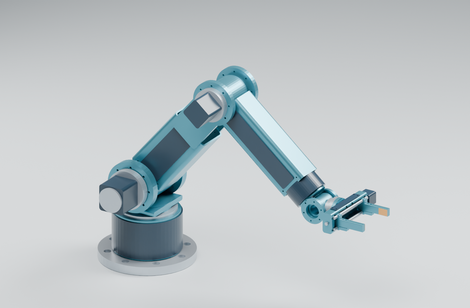
This folder contains INDRBT's reproducible mechanical design and generated models: 54 components and six complete pose assemblies.
Inspect the robot online to orbit, move joints, adjust the gripper, isolate parts and play the task without downloading files. Native files and reproduction steps below are optional for offline inspection or editing.
Public CAD download releaseSource file — choose the STEP/STL exchange pack or native FreeCAD saved-solid model; the same release includes PCB STEP and a combined offline inspection pack. The native-file guide explains units, geometry/history differences and application-opening instructions. The published GitHub Pages showcase includes the browser viewers and download controls.
Open the right file
| Purpose | File or folder | What it contains |
|---|---|---|
| Inspect the complete solid assembly | freecad/indrbt_home.FCStdSource file | FreeCAD home pose; 54 visible solids with descriptive labels, rigid groups and assumed materials |
| Exchange exact solid geometry | Home STEPSource file · all STEP filesSource file | Six positioned assemblies and 54 individual parts |
| Use triangle meshes | All STL filesSource file | Six assembly meshes and 54 individual part meshes; assembly meshes retain separate contacting bodies |
| Read the mechanism on GitHub | Mechanical tour · drawings | Rendered assembly, gripper, six poses and dimensioned interface drawings |
| Inspect the render scene | renders/indrbt_home.blendSource file | Blender scene using the exported CAD meshes |
| Move the robot and isolate a part | Public interactive viewer · optional offline copy | Online joint controls and playback; download only for offline use |
STEP, STL and FCStd links provide optional downloads for native inspection or editing. Use FreeCAD for the native model or STEP solids. After downloading on Windows, OPEN_FREECAD_MODEL.cmdSource file opens the native assembly and OPEN_3D_VIEWER.cmdSource file opens the offline browser viewer. PNG/SVG previews also display directly on GitHub.
Edit and regenerate
| Authoritative source | Role |
|---|---|
| config/robot.yaml | Shared SI configuration for dimensions, joint poses and engineering assumptions |
| build123d/parameters.pySource file | Converts configured lengths from metres to CAD millimetres |
| build123d/geometry.pySource file | Constructs the component solids and their interfaces |
| build123d/assembly.pySource file | Applies the six joint-frame transforms |
| build123d/export_all.pySource file | Exports STEP/STL, local meshes and CAD measurements |
| freecad/inspect_step.pySource file | Independently imports assembly STEP files and generates the native FreeCAD inspection assembly |
The Python geometry is parametric. The saved FreeCAD model is a solid export with inspection metadata, not the construction feature tree. For reproducible changes, edit the shared configuration or geometry source and regenerate. Save intentional manual FreeCAD edits under a separate filename; close older views without saving before replacing their generated file.
From 06_Complete_Project_Source, with the project's CAD dependencies, FreeCAD and Blender installed:
python scripts/generate_cad.py
python -m robotarm.demo --all
python scripts/refresh_cad.py
The final command refreshes native inspection, renders and CAD evidence. To audit saved outputs without regenerating them, run python scripts/review_cad.py. See the full workflow for tool discovery and overrides.
Coordinates and evidence
CAD lengths are millimetres; numerical kinematics use metres. Individual part files are authored in local groups base, j1 through j6. Open a complete assembly for positioned parts; assembly_meshes.json records local meshes and pose transforms. Motor, gearbox and bearing envelopes are simplified spatial representations with assumed materials.
CAD inspection, named-pose clearance and sampled-task clearance state what was checked. Drawings are concept interfaces rather than production drawings; geometric validity and sampled clearance do not establish hardware performance.
The numbered 01_CAD_ModelsSource file folder contains organized copies for browsing. Regenerate here, then use the source project's presentation sync to refresh those copies.